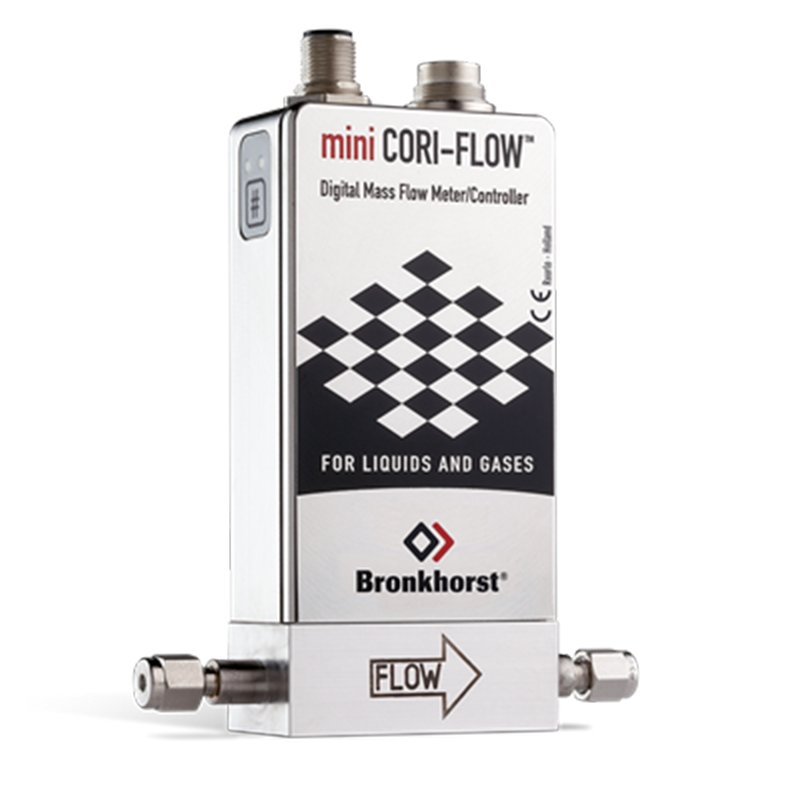
Bronkhorst mini CORI-FLOW™ M15 Low Flow Coriolis Mass Flow Meter / Controller
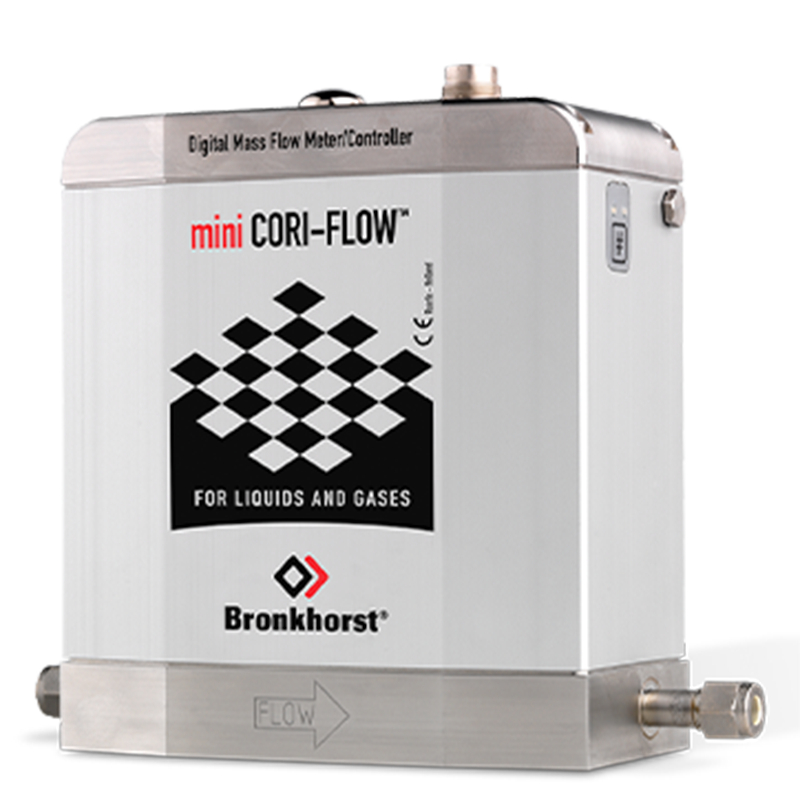
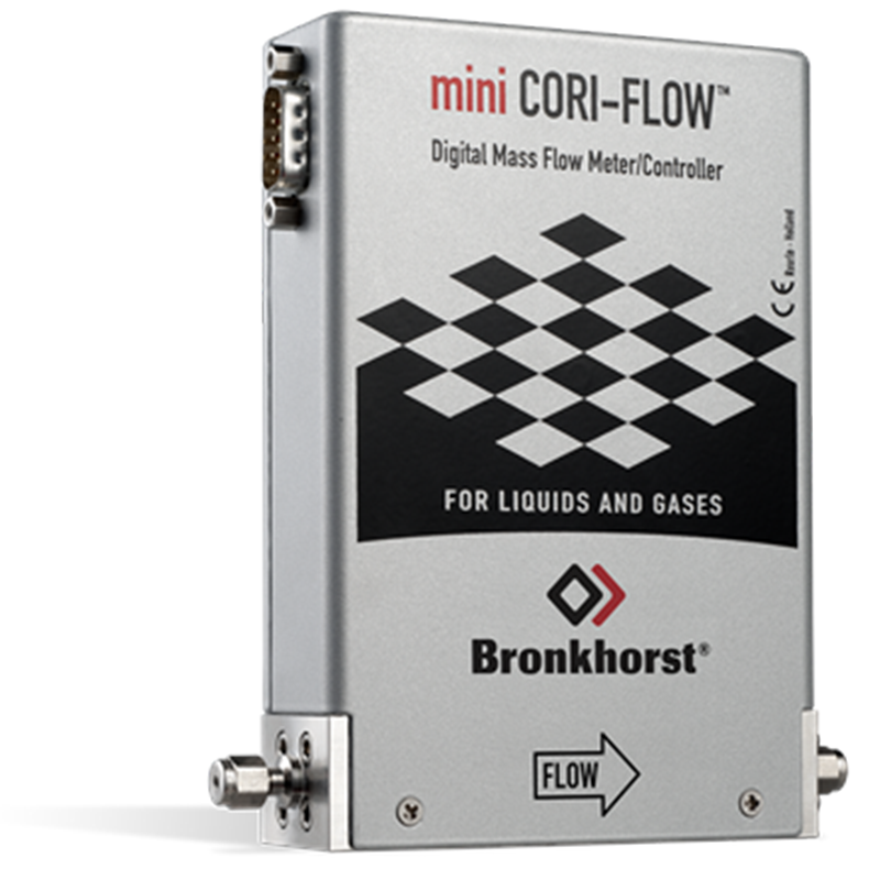
The mini CORI-FLOW™ Mass Flow Meters and Controllers from Bronkhorst® are precise and compact instruments based on the Coriolis measurement principle. They are designed to meet the needs of the low-flow market.
Low Flow Coriolis Mass Flow Meters / Controllers for Liquid and Gases
The mini CORI-FLOW™ Mass Flow Meters and Controllers from Bronkhorst® are precise and compact instruments based on the Coriolis measurement principle. They are designed to meet the needs of the low-flow market.
The Bronkhorst® model M15 Mass Flow Meter (MFM) is suitable for highly accurate measurement of gas or liquid flow in the range of 0 to 300 kg/h, which corresponds to 0 to 4000 ln/min when used with nitrogen. These instruments can operate at pressures up to 100 bar, with the possibility of higher pressure ratings upon request.
The instruments are equipped with a robust IP65 weatherproof housing and are optionally available with ATEX approval for use in Zone 2 hazardous areas.
The instrument contains a microprocessor-based PC-board with signal and fieldbus conversion, as well as a PID controller for optional mass flow control. This control can be achieved by means of a separately mounted control valve or pump.
Technical specifications
| Measurement / control system | |
| Flow rates | Liquid: 0…300 kg/h (nominal flow rate: 100 kg/h); Gas: 0…4000 ln/min (N2); Full Scale (FS) value is user-configurable |
| Mass flow accuracy | Liquid: ±0,2% Rd; Gas: ±0,5% Rd |
| Repeatability | ± 0,05 % of rate ± ½(ZS* x 100/actual flow)% |
| Turndown ratio | up to 1:100 |
| Zero stability (ZS) | < ± 50 g/h (Guaranteed at constant temperature and for unchanging process and environment conditions.) |
| Response time (sensor) | ≤ 200 msec |
| Temperature effect | on zero: < 5 g/h/°C; on span: < 0,001% Rd/°C; self heating (at zero flow): < 10°C (Depends on flow rate, heat capacity fluid, T amb., T fluid and cooling capacity.) |
| Operating temperature | 0 … 70 °C ; for ATEX Cat.3, Zone 2 max. 50°C |
| Mounting | any position, attitude sensitivity negligible. External shocks or vibrations should be avoided. |
| Temperature accuracy | ± 0,5 °C |
| Density accuracy | < ± 5 kg/m³ (at full scale flow) |
| Leak integrity, outboard | tested < 2 x 10⁻⁹ mbar l/s He |
| Warm-up time | > 30 min for optimum accuracy |
| Mechanical parts | |
| Sensor | single tube, DN 3.1 |
| Material (wetted parts) | stainless steel 316L / 1.4404 |
| Housing | stainless steel 430F |
| Pressure rating (PN) | 100 bar abs , higher on request |
| Process connections | compression type or face seal (VCR/VCO) couplings, or Tri-Clamp flanges (welded) |
| Seals | metal |
| Weight | 4.7 kg |
| Ingress protection | IP65 (weatherproof) |
| Electrical properties | |
| Power supply | +15…24 Vdc +/- 10% Max. ripple recommended: 50 mV tt |
| Max. power consumption | meter: max. 3 W; controller: max 7 W |
| Analog output | 0…5 (10) Vdc, min. load impedance > 2 kΩ; 0 (4)…20 mA (sourcing), max. load impedance < 375 Ω |
| Analog setpoint | 0…5 (10) Vdc, min. load impedance > 100 kΩ 0 (4)…20 mA (sourcing), max. load impedance ~ 250 Ω |
| Digital communication | standard: RS232; options: PROFIBUS DP, DeviceNet™, Modbus RTU or FLOW-BUS |
| Electrical connection | |
| Analog/RS232 | 8-pin DIN (male) |
| PROFIBUS DP | bus: 5-pin M12 (female); power: 8-pin DIN (male); |
| CANopen® / DeviceNet™ | 5-pin M12 (male) |
| FLOW-BUS/Modbus-RTU/ASCII | 5-pin M12 (male) |
| Control valve options | |
| M15+C0I: Gas flow control valve | Kv-max= 6,6 x 10⁻² |
| M15+C2I: Liquid flow control valve | Kv-max= 2,3 x 10⁻³ |
| M15+C5I: Gas/Liquid flow control valve | Kv-max= 6,6 x 10⁻² |
| M15+F-004AI: Gas/Liquid flow control | Kv-max= 3,0 x 10⁻¹ |
| M15+F-004BI: Gas/Liquid flow control | Kv-max= 1,0 |
Technical specifications subject to change without notice.
Download
Related products
Bronkhorst mini CORI-FLOW™ ML120V21 (Ultra) Low Flow Coriolis Mass Flow Controller
Bronkhorst mini CORI-FLOW ML120V00 (Ultra) Low Flow Coriolis Mass Flow Meter